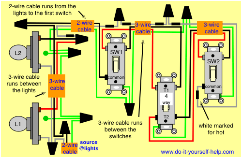
3 Way Switch Wiring Diagram Power At Switch Multiple Lights : Four Way Switch Diagrams / Option #1 is for power into the first switch, wire to the lights, and lastly wire from the light to the other switch.
3 Way Switch Wiring Diagram Power At Switch Multiple Lights : Four Way Switch Diagrams / Option #1 is for power into the first switch, wire to the lights, and lastly wire from the light to the other switch.. Power starting at the switch box this wiring diagram shows the power starting at the switch box where a splice is made with the hot line which passes the power to both switches, and up to the ceiling fan and light. This diagram illustrates wiring for a 4 way circuit with the electrical source at the light fixture and the switches coming after. The following 3 diagrams show the wiring for a specially made dimmer that can be used in these circuits in place of either of the the 3 way switches, or both. The power source is coming to light fitting first. The power source is coming to a light switch first.
The following 3 diagrams show the wiring for a specially made dimmer that can be used in these circuits in place of either of the the 3 way switches, or both. The power source is coming to a light switch first. 3 way dimmer switch wiring diagrams. This arrangement allows for lowering the lights in a 3 way circuit. The power source is coming to light fitting first.
3 Way And 4 Way Wiring Diagrams With Multiple Lights Do It Yourself Help Com from www.do-it-yourself-help.com This diagram illustrates wiring for a 4 way circuit with the electrical source at the light fixture and the switches coming after. The following 3 diagrams show the wiring for a specially made dimmer that can be used in these circuits in place of either of the the 3 way switches, or both. We can see that wire 1 and 2 on left are terminating at 3 and 6 on the right, while 3 and 6 on left are going on 1 and 2 on right, rest combination at 4,5,7 and 8 are same at both ends. This arrangement allows for lowering the lights in a 3 way circuit. There is a logic behind changing wire combination at 1,2,3 and 6 at both ends. Option #1 is for power into the first switch, wire to the lights, and lastly wire from the light to the other switch. 4 way switch wiring with light first. The power source is coming to light fitting first.
This option actually requires you to run two romex lines between the lights.
The following 3 diagrams show the wiring for a specially made dimmer that can be used in these circuits in place of either of the the 3 way switches, or both. The power source is coming to a light switch first. 3 way dimmer switch wiring diagrams. This option actually requires you to run two romex lines between the lights. Option #1 is for power into the first switch, wire to the lights, and lastly wire from the light to the other switch. Power starting at the switch box this wiring diagram shows the power starting at the switch box where a splice is made with the hot line which passes the power to both switches, and up to the ceiling fan and light. 4 way switch wiring with light first. There is a logic behind changing wire combination at 1,2,3 and 6 at both ends. We can see that wire 1 and 2 on left are terminating at 3 and 6 on the right, while 3 and 6 on left are going on 1 and 2 on right, rest combination at 4,5,7 and 8 are same at both ends. This diagram illustrates wiring for a 4 way circuit with the electrical source at the light fixture and the switches coming after. The ground wire is pigtailed with a wire connector at the switch boxes and the ceiling box. The power source is coming to light fitting first. This arrangement allows for lowering the lights in a 3 way circuit.
There is a logic behind changing wire combination at 1,2,3 and 6 at both ends. This diagram illustrates wiring for a 4 way circuit with the electrical source at the light fixture and the switches coming after. This arrangement allows for lowering the lights in a 3 way circuit. 3 way dimmer switch wiring diagrams. The following 3 diagrams show the wiring for a specially made dimmer that can be used in these circuits in place of either of the the 3 way switches, or both.
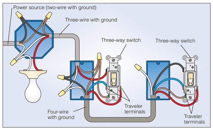
How To Wire A 3 Way Light Switch Diy Family Handyman from www.familyhandyman.com This diagram illustrates wiring for a 4 way circuit with the electrical source at the light fixture and the switches coming after. The following 3 diagrams show the wiring for a specially made dimmer that can be used in these circuits in place of either of the the 3 way switches, or both. We can see that wire 1 and 2 on left are terminating at 3 and 6 on the right, while 3 and 6 on left are going on 1 and 2 on right, rest combination at 4,5,7 and 8 are same at both ends. This option actually requires you to run two romex lines between the lights. Power starting at the switch box this wiring diagram shows the power starting at the switch box where a splice is made with the hot line which passes the power to both switches, and up to the ceiling fan and light. The ground wire is pigtailed with a wire connector at the switch boxes and the ceiling box. There is a logic behind changing wire combination at 1,2,3 and 6 at both ends. The power source is coming to light fitting first.
3 way dimmer switch wiring diagrams.
This diagram illustrates wiring for a 4 way circuit with the electrical source at the light fixture and the switches coming after. 4 way switch wiring with light first. The following 3 diagrams show the wiring for a specially made dimmer that can be used in these circuits in place of either of the the 3 way switches, or both. The power source is coming to light fitting first. This option actually requires you to run two romex lines between the lights. The power source is coming to a light switch first. Power starting at the switch box this wiring diagram shows the power starting at the switch box where a splice is made with the hot line which passes the power to both switches, and up to the ceiling fan and light. There is a logic behind changing wire combination at 1,2,3 and 6 at both ends. Option #1 is for power into the first switch, wire to the lights, and lastly wire from the light to the other switch. The ground wire is pigtailed with a wire connector at the switch boxes and the ceiling box. We can see that wire 1 and 2 on left are terminating at 3 and 6 on the right, while 3 and 6 on left are going on 1 and 2 on right, rest combination at 4,5,7 and 8 are same at both ends. This arrangement allows for lowering the lights in a 3 way circuit. 3 way dimmer switch wiring diagrams.
The power source is coming to light fitting first. This diagram illustrates wiring for a 4 way circuit with the electrical source at the light fixture and the switches coming after. The following 3 diagrams show the wiring for a specially made dimmer that can be used in these circuits in place of either of the the 3 way switches, or both. We can see that wire 1 and 2 on left are terminating at 3 and 6 on the right, while 3 and 6 on left are going on 1 and 2 on right, rest combination at 4,5,7 and 8 are same at both ends. This arrangement allows for lowering the lights in a 3 way circuit.
How To Wire A 3 Way Light Switch Diy Family Handyman from www.familyhandyman.com The following 3 diagrams show the wiring for a specially made dimmer that can be used in these circuits in place of either of the the 3 way switches, or both. 4 way switch wiring with light first. The ground wire is pigtailed with a wire connector at the switch boxes and the ceiling box. There is a logic behind changing wire combination at 1,2,3 and 6 at both ends. 3 way dimmer switch wiring diagrams. The power source is coming to light fitting first. This diagram illustrates wiring for a 4 way circuit with the electrical source at the light fixture and the switches coming after. Option #1 is for power into the first switch, wire to the lights, and lastly wire from the light to the other switch.
The ground wire is pigtailed with a wire connector at the switch boxes and the ceiling box.
The power source is coming to light fitting first. The following 3 diagrams show the wiring for a specially made dimmer that can be used in these circuits in place of either of the the 3 way switches, or both. This arrangement allows for lowering the lights in a 3 way circuit. 4 way switch wiring with light first. This diagram illustrates wiring for a 4 way circuit with the electrical source at the light fixture and the switches coming after. Power starting at the switch box this wiring diagram shows the power starting at the switch box where a splice is made with the hot line which passes the power to both switches, and up to the ceiling fan and light. The ground wire is pigtailed with a wire connector at the switch boxes and the ceiling box. The power source is coming to a light switch first. This option actually requires you to run two romex lines between the lights. Option #1 is for power into the first switch, wire to the lights, and lastly wire from the light to the other switch. 3 way dimmer switch wiring diagrams. We can see that wire 1 and 2 on left are terminating at 3 and 6 on the right, while 3 and 6 on left are going on 1 and 2 on right, rest combination at 4,5,7 and 8 are same at both ends. There is a logic behind changing wire combination at 1,2,3 and 6 at both ends.
Power starting at the switch box this wiring diagram shows the power starting at the switch box where a splice is made with the hot line which passes the power to both switches, and up to the ceiling fan and light 3 way switch wiring. There is a logic behind changing wire combination at 1,2,3 and 6 at both ends.


0 Komentar